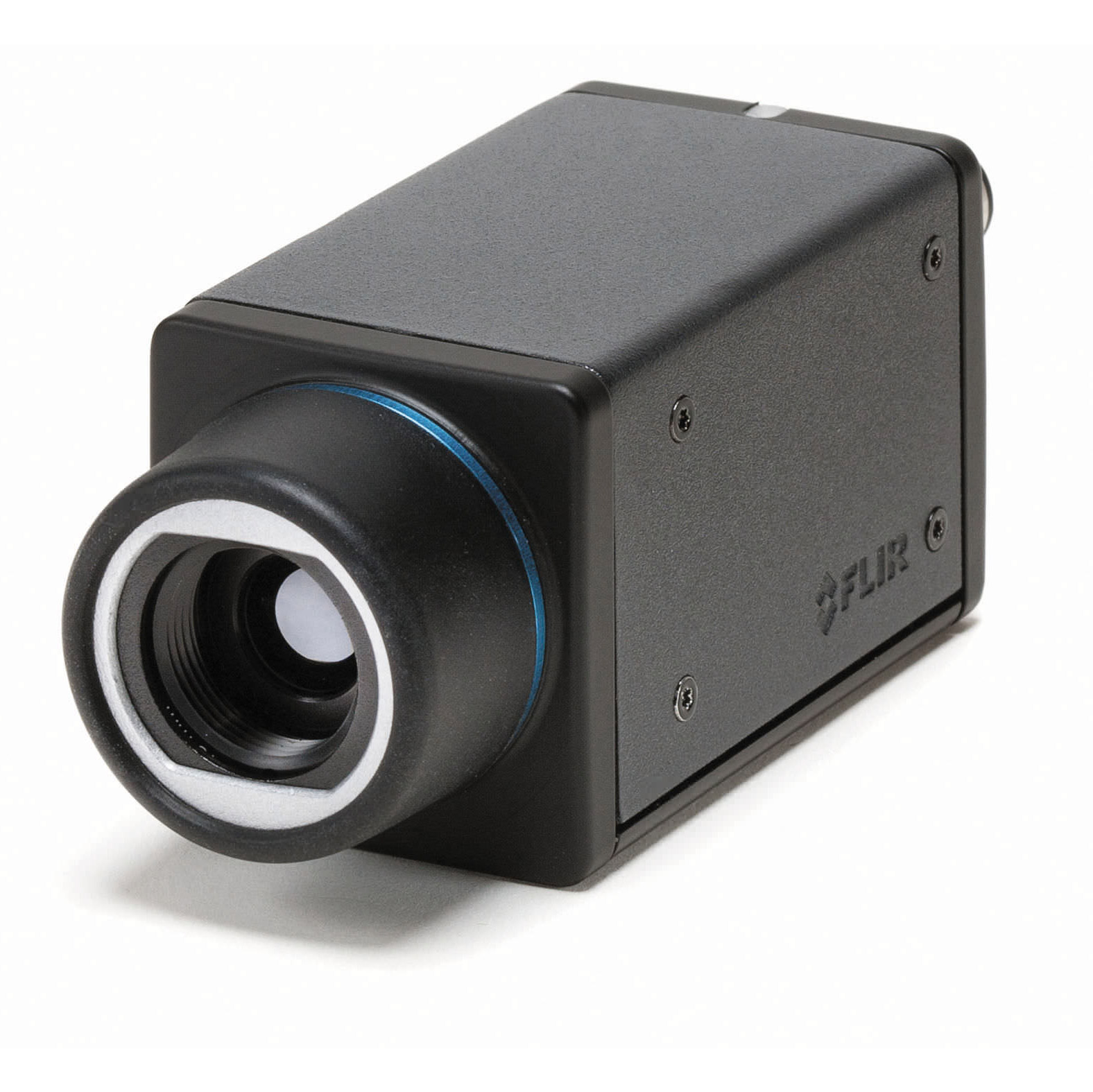
FLIR A35/65sc
IR-upplösning 320 x 256
För enklare R&D applikationer kan FLIRs Ax5 serie var ett kostnadseffektivt alternativ.
Beskrivning
Specifikationer av FLIR A35/65sc
FLIR A65 & A35 Technical Specifications
| System Overview | FLIR A65 | FLIR A35 |
|---|---|---|
| IR resolution | 640 × 512 pixels | 320 × 256 pixels |
| Field of View (FOV) | 90° × 69° with 7.5 mm lens | 63° × 50° with 7.5 mm lens |
| 45° × 37° with 13 mm lens | 48° × 39° with 9 mm lens | |
| 25° × 20° with 25 mm lens | 24° × 19.2° with 19 mm lens | |
| 12.4° × 9.92° with 50 mm lens | 13° × 10.8° with 35 mm lens | |
| 6.2° × 4.96° with 100 mm lens | 7.6° × 6.08° with 60 mm lens | |
| Image frequency | 30 Hz | 60 Hz |
| Detector data | ||
| Detector pitch | 17 µm | 25 µm |
| Measurement | ||
| Object temperature range | -25°C to 135°C (-13 to 275°F) / –40°C to 550°C (-40 to 1022°F) | |
General
| Imaging & Optical Data | |
|---|---|
| Thermal sensitivity/NETD | < 0.05°C @ 30°C (86°F) / 50 mK |
| Accuracy | Accuracy ±5°C (±9°F) or ±5% of reading |
| F-number | 1.25 |
| Focus | Fixed |
| Detector data | |
| Focal Plane Array (FPA) / Spectral range | Uncooled VOX microbolometer / 7.5–13 µm |
| Detector time constant | Typical 12 ms |
| Ethernet | |
| Ethernet | Control and image |
| Ethernet, type | Gigabit Ethernet |
| Ethernet, standard | IEEE 802.3 / RJ-45 |
| Ethernet, communication | GigE Vision ver. 1.2 Client API GenICam compliant |
| Ethernet, image streaming | 8-bit monochrome @ 7.5 / 30 / 60 Hz (variant dependant) Signal linear/ DDE, Automatic/ Manual, Flip H&V 14-bit @ 7.5 / 30 / 60 Hz (variant dependent) according to IR camera resolution Signal linear/ DDE, GigE Vision and GenICam compatible |
| Ethernet, power | Power over Ethernet, PoE IEEE 802.3af class 0 Power |
| Ethernet, protocols | TCP, UDP, ICMP, IGMP, DHCP, GigEVision |
| Digital input/output | |
| Digital input | General purpose , 1× opto-isolated, “0” < 2, “1”=2–12 VDC |
| Digital output, purpose | General purpose output to ext. device (programmatically set) |
| Digital output | 1× opto-isolated, 2–40 VDC, max 185 mA |
| Digital I/O, isolation voltage | 500 VRMS |
| Digital I/O, supply voltage | 2–40 VDC, max 200 mA |
| Digital I/O, connector type | 12-pole M12 connector (shared with Digital Synchronization and External power) |
| Synchronization In, purpose | Frame sync in to control camera |
| Synchronization In | 1×, non-isolated |
| Synchronization In, type | LVC Buffer @3.3V, “0” <0.8 V, “1”>2.0 V. |
| Synchronization Out, purpose | Frame sync out to control another Ax5 camera |
| Synchronization Out | 1×, non-isolated |
| Synchronization Out, type | LVC Buffer @ 3.3V, ”0”=24 MA max, “1”= –24 mA max. |
| Digital Synchronization, connector type | 12-pole M12 connector (shared with Digital I/O and External power) |
| Power system | |
| External power operation | 12/24 VDC, < 3.5 W nominal < 6.0 W absolute max |
| External power, connector type | 12-pole M12 connector (shared with Digital I/O and Digital Synchronization ) |
| Voltage | Allowed range 10–30 VDC |
| Environmental data | |
| Operating temperature range | –15°C to 60°C (+5°F to 140°F) |
| Storage temperature range | –40°C to 70°C (–40°F to 158°F) |
| Humidity (operating and storage) | IEC 60068-2-30/24 h 95% relative humidity 25°C to 40°C (77°F to 104°F) |
| EMC | EN 61000-6-2 (Immunity) EN 61000-6-3 (Emission) FCC 47 CFR Part 15 Class B (Emission) |
| Encapsulation | IP 40 (IEC 60529) |
| Bump | 25 g (IEC 60068-2-27) |
| Vibration | 2 g (IEC 60068-2-6 & MIL-STD810G) |
| Physical data | |
| Weight | 0.21 kg (0.46 lb.) |
| Camera size (L × W × H) | 106 × 47 × 50 mm (4.2 × 1.9 × 2.0 in.) |
| Tripod mounting | UNC ¼”-20 (on three sides) |
| Base mounting | 4 × M3 thread mounting holes (bottom) |
| Housing material | Magnesium and aluminum |
| Scope of delivery | |
| Packaging, contents | Cardboard box, thermal imaging camera with lens, focus adjustment tool, printed documentation, user documentation CD-ROM, FLIR Tools download card |

